
Revision history (1 updates, last updated Sep 1, 2026)
A log of the changes made to this article. Where a pre-update version was archived, it stays readable at a permanent DOI link.
- Retranslated as a full translation of the Japanese original. The previous English version was an abridgement that carried only part of the source, so sections, tables, Mermaid diagrams, figure captions and FAQ entries were missing. All of them have been restored to match the Japanese original, and the technical claims are the same as in the Japanese version. Read the version before this update (DOI: 10.5281/zenodo.21614453)
- First published
Cite this article(DOI (registered archive): 10.5281/zenodo.21614452)
The DOIs below refer to previously archived versions and may not match the current text. Use this page’s URL to reference the current text.
Go Komura (2026). An Introduction to HCP Charts and MakingHCPChartSkill. KomuraSoft LLC. https://comcomponent.com/en/blog/2026/02/22/000-what-is-hcp-chart-and-making-hcp-chart-skill/
- DOI (registered archive)
- 10.5281/zenodo.21614452
- DOI (last registered version)
- 10.5281/zenodo.22217118
Table of Contents
- What Is an HCP Chart?
- The Problem This Repository Solves
- The Fastest Way to Grasp the Repository Layout
- A 10-Minute Hands-On (GCD Sample)
- How to Read the Two Samples
- What Happens Inside (HCP Chart)
- Conclusion
If you want HCP charts to be diagrams that can be read as specifications, hand-drawn diagrams alone are hard to keep in working order.
MakingHCPChartSkill is a skill repository for interpreting HCP-DSL (text) according to the specification and returning deterministic SVG (deterministic meaning that the same input always produces the same SVG).
In this article, we start from the basics of HCP charts and go all the way through actually running the tool.
In the diagram a solid line marks a relation that always holds and a dashed line marks a conditional one (the conditions are given per relation on the detail page). The full list of relations (14 in total, with evidence and certainty) and the definitions of the main concepts are collected on the knowledge map detail page (in Japanese). Data: JSON-LD / Turtle
1. What Is an HCP Chart?
An HCP chart is a notation for describing processing hierarchically. In this repository, the following writing style is treated as a mandatory rule.
- The left side states what to achieve (the goal)
- The right side (deeper indentation) states how to achieve it (means and details)
- The top level (level 0) carries a goal label
Writing text along these rules makes the correspondence between design intent and implementation detail easy to read.
flowchart TB
    accTitle: Basic rules for writing an HCP chart
    accDescr: Level 0 at the top carries only a goal label, the left side states what to achieve and the deeper indentation on the right states how to achieve it, which makes the correspondence between design intent and implementation detail readable.
    l0["Level 0 holds only the goal label"] --> goal["Left side is the goal (what to achieve)"]
    goal --> means["Right side is the means (how to achieve it)"]
    means -.-> effect["Design intent maps to implementation detail"]
Figure 1: An HCP chart describes processing hierarchically, with the goal on the left and the means at deeper indentation on the right.
1.1. Where HCP Comes From, and How It Differs from Other Notations
HCP stands for Hierarchical ComPact description chart, a notation created at the Yokosuka Electrical Communication Laboratory of Nippon Telegraph and Telephone Public Corporation (now NTT). In other words, it is not a term coined by this article or this repository, but a notation that has already been in use in Japan. Its characteristics are that processing can be written hierarchically, that the relationship between data and processing is easy to annotate, that it is easy to draw freehand, and that a single sheet holds a lot of content because descriptions sit next to the symbols rather than inside boxes.
Lining it up against other notations makes its position easier to see.
| Notation | How it expresses structure | Difference from an HCP chart |
|---|---|---|
| Flowchart | Lays out steps as boxes and follows the flow along the lines | It cannot express the hierarchy of which step is a detail of which. As branches multiply, the lines tend to cross |
| NS chart (structured chart) | Expresses structure with nested rectangles | Because descriptions go inside the boxes, deep hierarchies and long descriptions tend to run out of horizontal space |
| PAD | A tree structure that refines from left to right | The goal-on-the-left, means-on-the-right direction is close to the idea behind HCP. HCP is centered on circular symbols and places descriptions to the right of each symbol |
With that in mind, what is specific to MakingHCPChartSkill, the subject of this article, is not the notation itself but the following two things.
- HCP-DSL, a way to write HCP charts as text, and its interpretation specification (
references/hcpchartspec.md) - The description granularity convention, which says that level 0 carries only goal labels and that code-like descriptions such as assignments and comparisons are pushed down to child nodes. This is a mandatory rule that the repository itself defines, not a rule of HCP charts in general
flowchart TB
    accTitle: Separating the general notation from the repository-specific parts
    accDescr: The HCP chart notation itself is an existing notation created at the Yokosuka Electrical Communication Laboratory, and the only repository-specific parts are HCP-DSL with its interpretation specification and the description granularity convention.
    general["HCP chart (an existing notation)"] --> repo["Parts specific to MakingHCPChartSkill"]
    repo --> dsl["HCP-DSL and its interpretation spec"]
    repo --> conv["Description granularity convention"]
    conv -.-> rule["Level 0 holds only the goal label"]
Figure 2: The notation itself has been around for a long time. The only repository-specific parts are HCP-DSL and the description granularity convention.
1.2. How to Write HCP-DSL (Syntax Quick Reference)
The table below covers most of what you need. The full specification lives in references/hcpchartspec.md, and references/hcp-chart-schema.md collects just the key points.
Kinds of lines
| Line form | How it is handled |
|---|---|
| Blank line | Ignored |
A line that starts (ignoring leading whitespace) with # |
Treated as a comment and ignored |
A line that starts (ignoring leading whitespace) with \ or ¥ |
A command line. The command name runs up to the first ASCII space, and everything after it is arguments |
| Anything else | Drawn as an ordinary processing node (a circle) |
Indentation (hierarchy)
| Rule | Detail |
|---|---|
| Unit of one level | One tab, or four ASCII spaces |
| Partial indentation | Increments such as two spaces produce an error |
| Going deeper all at once | Going two or more levels deeper than the previous line produces an error. Descend one level at a time |
Commands
| Command | Meaning | Notes |
|---|---|---|
\title / \author / \date / \version |
Header information | Written before \module they apply to every module; written after it they override the values for that module only |
\module <name> |
Start of a module | Required. Can appear only at level 0. A duplicate module name is an error |
\mod <label> |
Call to a module or function | Drawn as a double circle |
\repeat <label> |
Iteration | Write the body of the loop one level deeper |
\fork <label> |
Parent of a branch (dispatch) | Place the branches directly beneath it |
\true <label> / \false <label> |
The two arms of a boolean branch | Allowed only directly beneath a \fork, exactly one level deeper. If no ancestor is a \fork, it is an error |
\branch <condition> |
An arm of a multi-way branch that is not boolean | Same as above |
\return [n] |
Exit | n is an optional integer |
\ec <label> / \ex <label> |
Error check / error exit | In the current version these only affect drawing and carry no control semantics |
\data <name> |
Data definition | The name cannot contain spaces or . (it is an error if it does) |
\in <name> / \out <name> |
Annotation for input and output data | Treated as an annotation on the parent node one level up |
A minimal example looks like this. Start with \module, put the goal on the left, and put the means on the right.
\module main
Receive the input and check the prerequisites
    Confirm that the value is a positive integer
\fork is the input valid
    \true yes
        Run the main processing
    \false no
        Return an error to the caller
        \return
Return the result
flowchart TB
    accTitle: The flow described by the minimal DSL example
    accDescr: Starting from module, the flow checks the prerequisites of the input, uses fork to branch on whether the input is valid, runs the main processing and returns the result when it is valid, and returns an error to the caller when it is not.
    m["Start of module main"] --> pre["Receive the input and check prerequisites"]
    pre --> fork{"Is the input valid"}
    fork -->|"Yes"| main["Run the main processing"]
    fork -->|"No"| err["Return an error (return)"]
    main --> ret["Return the result"]
Figure 3: The flow of the minimal example. Start from module, put the goal on the left, and line up the true and false arms directly beneath fork.
2. The Problem This Repository Solves
When diagrams alone are managed by hand, problems like these tend to occur.
- The diagram and the specification text drift apart
- Constraints on branching and hierarchy become vague
- Diff reviews are difficult
With MakingHCPChartSkill, you pass HCP-DSL as a JSON request, and hcp_render_svg.py performs the validation and the drawing.
The same input always yields the same output, which makes it easy to incorporate the diagrams into CI and reviews.
flowchart TB
    accTitle: Problems with hand-drawn diagrams and the fix that text-based management brings
    accDescr: Managing diagrams by hand alone causes drift from the specification text and makes diff review hard, whereas passing HCP-DSL as a JSON request lets hcp_render_svg.py validate and draw it so that the same input yields the same SVG.
    hand["Diagrams managed by hand alone"] -.-> issue["Drift, vagueness, hard diff review"]
    dsl["Pass HCP-DSL as a JSON request"] --> render["hcp_render_svg.py validates and draws"]
    render --> svg["A deterministic SVG comes back"]
    svg --> ci["Can be wired into CI and review"]
Figure 4: Because SVG is generated deterministically from HCP-DSL text instead of drawn by hand, the diagrams fit into diff review and CI.
3. The Fastest Way to Grasp the Repository Layout
Target repository: https://github.com/gomurin0428/MakingHCPChartSkill
hcp-chart-svg-v2/SKILL.mdHow to use the skill and its constraints (for example,renderAllModulesandmodulecannot be specified together).hcp-chart-svg-v2/scripts/hcp_render_svg.pyThe core script that validates the JSON input, interprets the HCP-DSL, and returns the SVG response.hcp-chart-svg-v2/references/Specification reference, sample request and response, sample SVG.hcp-chart-svg-v2/scripts/hcp_xml_to_svg.pyDeprecated. Usehcp_render_svg.pynow.
flowchart TB
    accTitle: The main files in the repository
    accDescr: Under hcp-chart-svg-v2 there is SKILL.md describing how to use the skill and its constraints, the core script hcp_render_svg.py, and references holding the specification and samples, while the old script hcp_xml_to_svg.py is deprecated.
    root["hcp-chart-svg-v2"] --> skill["SKILL.md (usage and constraints)"]
    root --> script["hcp_render_svg.py under scripts"]
    root --> refs["references (spec and samples)"]
    script -.-> old["hcp_xml_to_svg.py is deprecated"]
Figure 5: The entry point is SKILL.md, the core is hcp_render_svg.py, and the specification and samples sit under references.
4. A 10-Minute Hands-On (GCD Sample)
Prerequisites
| Item | Details |
|---|---|
| Python | hcp_render_svg.py runs on Python 3. The repository does not state a minimum version, but since it uses dataclasses and from __future__ import annotations, it works on 3.7 or later |
| Additional packages | None needed. It uses argparse / json / logging / math / re / sys / dataclasses / pathlib / typing / xml.sax.saxutils, all of which are standard library modules |
| Shell | The commands below assume Windows PowerShell. If the output is garbled, make UTF-8 explicit before running with $env:PYTHONUTF8 = "1" and chcp 65001 |
| Codex | Needed only if you install the skill as described in 4.2. If you do not use Codex, you can skip 4.2 (everything from 4.3 on works with the script alone) |
4.1. Clone the Repository
git clone https://github.com/gomurin0428/MakingHCPChartSkill.git
cd .\MakingHCPChartSkill
4.2. Install the Skill into Your Local Codex
Codex here means OpenAI’s coding agent. $HOME\.codex (C:\Users\<username>\.codex on Windows) is its configuration directory, and the repository README describes copying the whole directory into skills\<skill name> underneath it. With that in place, when you ask the agent to draw an HCP chart, it calls the renderer following the steps in this SKILL.md.
Copy-Item -Recurse -Force .\hcp-chart-svg-v2 "$HOME\.codex\skills\hcp-chart-svg-v2"
This step is not mandatory. The renderer is a standalone script that takes --input and --output, so if you do not use Codex, go straight to 4.3.
4.3. Generate the SVG Response from the Sample Input
python .\hcp-chart-svg-v2\scripts\hcp_render_svg.py `
  --input .\hcp-chart-svg-v2\references\example-gcd-request.json `
  --output .\hcp-chart-svg-v2\references\example-gcd-response.json `
  --pretty
4.4. Extract the SVG from the Response JSON
$r = Get-Content -Raw .\hcp-chart-svg-v2\references\example-gcd-response.json | ConvertFrom-Json
$r.svg | Set-Content -NoNewline -Encoding utf8 .\hcp-chart-svg-v2\references\example-gcd.svg
flowchart TB
    accTitle: The path from the hands-on to an SVG file
    accDescr: Shows the sequence of passing the sample request JSON to hcp_render_svg.py, producing a response JSON, pulling out its svg property, and saving it as an SVG file.
    req["Sample request JSON"] --> py["Run hcp_render_svg.py"]
    py --> res["A response JSON is written out"]
    res --> ext["Pull out the svg property"]
    ext --> file["Save it as an SVG file"]
Figure 6: The hands-on flow. Pass the request JSON to the script, then write the svg from the response out to a file.
4.5. Notes (Input Constraints)
- When
renderAllModules=true,modulecannot be specified. - If
diagnosticscontains anerror,svgorsvgswill be empty.
5. How to Read the Two Samples
When you open one of the diagrams, read it by moving your eyes in the following order.
- Read only the leftmost column, from top to bottom. What sits there is what to achieve (the goals), and it forms the outline of the whole process
- Follow any line that catches your attention to the right. What lines up at deeper indentation on the right is how that goal is achieved (the means and details)
- Check parent and child along the vertical lines (the trunks). A trunk connects steps at the same depth, and it is drawn so that it does not pass through a line at a shallower depth
flowchart TB
    accTitle: How to move your eyes when reading an HCP chart
    accDescr: Shows the three-step reading order of first reading the leftmost column from top to bottom to grasp the outline, then following a line of interest to the right to check the means and details, then confirming parent and child relationships along the vertical trunks.
    s1["Read the leftmost column top to bottom"] --> a1["Grasp the outline of the whole process"]
    a1 --> s2["Follow a line of interest to the right"]
    s2 --> a2["Check the means and details"]
    a2 --> s3["Confirm parent and child along the trunk"]
Figure 7: Grasp the outline from the leftmost column of goals first, then descend into the means on the right only for the lines you need.
The symbols mean the following.
| Symbol | Meaning |
|---|---|
| Circle | An ordinary processing step |
| Double circle | A call to a module or function (\mod) |
| Circle with a loop arrow | Iteration (\repeat) |
| Circle with a right-pointing triangle | Parent of a branch (\fork) |
| Arrow leaving the trunk to the right | An arm of a branch (\branch / \true / \false). The condition is written to the right of the arrow |
| Downward-pointing triangle | Exit (\return) |
| Circle with an x inside | Error check (\ec) |
| Two small circles | Error exit (\ex) |
5.1. Euclid’s Algorithm (GCD)
- Sample input:
example-gcd-request.json - Sample output:
example-gcd-response.json
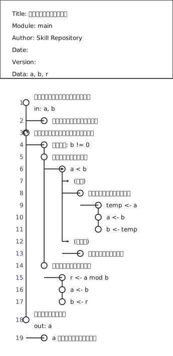
Receiving the input, iterating, and returning are separated hierarchically, which makes the goals and the means of the processing easy to follow.
Reading only the leftmost column gives three lines: receive the input values and prepare for the computation, close in on the greatest common divisor while a remainder is left, return the result to the user. That alone tells you the outline of the algorithm. A concrete computation such as r <- a mod b is pushed one more level of indentation to the right, beneath the step inside the loop that decides the values to carry into the next iteration. This positional relationship is exactly the correspondence between goal (left) and means (right). If r <- a mod b showed up in the leftmost column, that would be a sign that the description granularity convention from 1.1 has been violated.
flowchart TB
    accTitle: The outline shown by the leftmost column of the GCD sample
    accDescr: The leftmost column of the GCD sample is three lines that receive the input values and prepare for the computation, close in on the greatest common divisor while a remainder is left, and return the result to the user, while the concrete computation is pushed further to the right.
    g1["Receive the input values and prepare"] --> g2["Close in while a remainder is left"]
    g2 --> g3["Return the result to the user"]
    g2 -.-> d1["The concrete computation goes further right"]
Figure 8: The leftmost column of the GCD sample. Three lines give the outline of the algorithm, and the computational detail moves to the right.
The Data: line at the top of the diagram and the in: / out: annotations attached below the nodes are further reading aids. In this diagram, in: a, b and out: a are attached, so the entry point and the exit point are visible from the diagram alone.
5.2. Order Approval Flow
- Sample input:
example-order-approval-request.json - Sample output:
example-order-approval-response.json
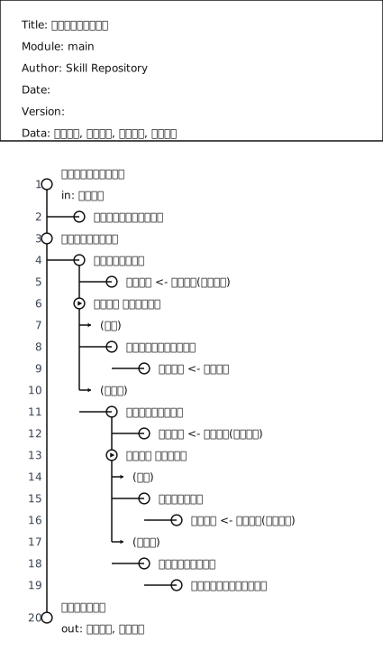
Even for business workflows, fork and true/false let you describe the intent of each branch clearly.
Here too, the leftmost column is only three lines: accept the order details, decide whether shipment is possible, return the result of the processing. Implementation-level operations such as checking stock, submitting an approval request, and registering the shipment all sit at deeper indentation on the right. Branches are arrows leaving the trunk to the right, with the processing for each case hanging below (yes) and (no). The business decision - send it back if the item is out of stock, arrange shipment if it is approved, otherwise put it on hold - can be followed just by tracing the arrows out of the two branch points.
flowchart TB
    accTitle: The business decision branches in the order approval sample
    accDescr: Shows that accepting the order details and deciding whether shipment is possible leads to a business decision expressed by two branches that send the order back when stock is missing, arrange shipment when it is approved, and put it on hold otherwise.
    o1["Accept the order details"] --> o2["Decide whether shipment is possible"]
    o2 --> f1{"Is the item out of stock"}
    f1 -->|"Yes"| back["Send it back"]
    f1 -->|"No"| f2{"Is it approved"}
    f2 -->|"Yes"| ship["Arrange shipment"]
    f2 -->|"No"| hold["Put it on hold"]
Figure 9: The business decision in the order approval sample. Tracing the two branches is enough to see where sending back, arranging shipment, and holding lead.
In a review of a business specification, this makes it easy to split the work: read the leftmost column together with the stakeholders, and settle the details on the right with the implementers.
6. What Happens Inside (HCP Chart)
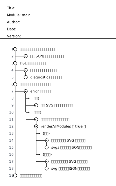
Written in HCP-DSL, the processing flow of execute_request looks like this.
\module main
Receive the request and check the prerequisites
    Validate the required fields of the input JSON
Parse the DSL into a structure
    Interpret the modules and hierarchy
    Collect diagnostics
Choose the response path based on the diagnostics
    \fork does an error exist
        \true yes
            Return empty SVG-related payloads
        \false no
            Determine the modules to render
            \fork is renderAllModules true
                \true yes
                    Generate SVG for all modules
                    Assemble the response JSON containing svgs
                \false no
                    Generate SVG for a single module
                    Assemble the response JSON containing svg
Return the result to the caller
Here is the diagram produced by actually rendering the DSL above.
7. Conclusion
The strength of HCP charts is not just that they are easy to read as diagrams - they can be managed in a form you can treat as a specification.
With MakingHCPChartSkill, you can validate HCP-DSL and generate the SVG from it end to end.
As a next step, write one of your everyday processing specifications in HCP-DSL and refine it while watching diagnostics - that is the easiest way to feel the benefit of adopting it.
References
- MakingHCPChartSkill
- hcp-chart-svg-v2/SKILL.md
- hcp-chart-svg-v2/scripts/hcp_render_svg.py
- hcp-chart-svg-v2/references/hcpchartspec.md (the complete DSL specification)
- hcp-chart-svg-v2/references/hcp-chart-schema.md (the key points of the syntax)
- HCP chart - Wikipedia, in Japanese (formal name and origin)
Related Articles
Recent articles sharing the same tags. Deepen your understanding with closely related topics.
Practical Multithreading Best Practices: Java Edition — Conventions for the Virtual Thread Era
Run Java tasks on ExecutorService and virtual threads, not raw threads. Covers synchronized vs. ReentrantLock, cooperative stopping via i...
Practical Multithreading Best Practices: C Edition — Writing Safely the Win32 API Way
In C on Win32 the established practice is _beginthreadex, SRW locks and condition variables, Interlocked, and a stop event plus WaitForMu...
Practical Multithreading Best Practices: C++ Edition — Designing Failures Out with RAII and jthread
C++ data races are undefined behavior. Learn the std::thread destructor trap, stopping with jthread and stop_token, scoped_lock, atomic's...
Practical Multithreading Best Practices: .NET Edition — What to Decide Before You Add More Threads
Keep .NET/C# threads from crashing or hanging. Ride on Task, cut shared mutable state, lock with discipline, stop with CancellationToken,...
Never Use a QR Code's Decoded Value As-Is — Error Correction Succeeding Does Not Guarantee the Value
QR error correction does not guarantee the decoded value. Sample images and two decoders show why dirt can yield a different value, and w...
Related Topics
These topic pages place the article in a broader service and decision context.
Windows Technical Topics
Topic hub for KomuraSoft LLC's Windows development, investigation, and legacy-asset articles.
Where This Topic Connects
This article connects naturally to the following service pages.
Technical Consulting & Design Review
This topic is about organizing designs and processing flows into a visible form, so it fits naturally in the context of technical consulting and design review.
Frequently Asked Questions
Common questions about the topic of this article.
- What is an HCP chart?
- It is a notation for describing processing hierarchically. The left side states what to achieve (the goal), the right side at deeper indentation states how to achieve it (means and details), and the top level (level 0) carries a goal label. Writing text along these rules makes the correspondence between design intent and implementation detail easy to read.
- What does MakingHCPChartSkill do?
- It is a skill repository that interprets HCP-DSL (text) according to the specification and returns deterministic SVG. When you pass HCP-DSL as a JSON request, hcp_render_svg.py performs the validation and the drawing. The same input always yields the same output, which makes the diagrams easy to wire into CI and reviews.
- How is this different from managing diagrams by hand?
- When diagrams alone are managed by hand, the diagram and the specification text tend to drift apart, constraints on branching and hierarchy become vague, and diff reviews get difficult. Generating SVG deterministically from HCP-DSL text lets you manage diagrams in a form you can treat as a specification, and refine them while watching diagnostics.
- Are there constraints on using it?
- When renderAllModules=true, you cannot also specify module. And if diagnostics contains an error, svg or svgs will be empty. As for the scripts, hcp_xml_to_svg.py is deprecated, and hcp_render_svg.py is the one to use now.